Plastic Part Design Factors
When designing plastic parts for injection molding, there are three critical factors to consider: mold complexity, moldability, and part function. If each of these components is taken into consideration during the plastic design and manufacturing process, you will be able to design plastic parts that are functional, strong, and affordable to produce. Therefore, plastic part design and manufacturing expertise are needed to make your plastic design vision a reality. When developing a part design for injection molding, Integrated Molding Solutions provides our extensive industry knowledge to help businesses avoid plastic manufacturing pitfalls in order to design plastics that maintain the integrity of their vision and keep profit margins high.
Mold Complexity in Plastic Design for Injection Molding
The first component of successful plastic design is mold complexity. Mold complexity refers to the intricacy of the steel mold tooled to mold your part. The more complex the mold for your plastic design, the more expensive tooling will be. For large-scale projects, investing more in tooling may be worth the additional upfront costs. For smaller-scale projects, however, it is worth finding creative workarounds to make your plastic design for injection molding less complex. Additive manufacturing through 3D printing is one possibility for small-scale projects. If your plastic design requires injection molding, one of the easiest ways to tweak your part design is to avoid undercuts.
Undercuts
Undercuts are any features of the plastic design that prevent the part from being ejected from the mold, or any places in the part where the plastic design gets smaller and then expands again. If an undercut is included in the plastic design, the cost of tooling will rise significantly, as the steel injection mold has to collapse in on itself to release the part. Undercuts can be avoided by including a cut-out or hole underneath the plastic component that would cause the undercut. IMS engineers will help your business design plastics to avoid issues caused by undercuts in plastic injection molding.
Draft Angle
Another aspect of plastic design that can increase mold complexity is ensuring the correct draft angle is in place in tooling the mold. Draft angle in plastic design for injection molding refers to the slope of the sides of most features of injection molded parts and the slope of the steel mold itself. The deeper the mold for a plastic part, the greater the draft angle needs to be, so that the plastic part ejects cleanly without scraping against the steel injection mold. This slope prevents the plastic part from being parallel to the motion of the mold opening. Without draft angle, the plastic design will be compromised, and the plastic part may come out damaged. Further, lack of draft angle may cause damage to the mold during the plastic manufacturing process, which is costly and time consuming to repair. Ideal draft angle for plastic design is one to two degrees for most parts, though parts with deep holes or highly textured surfaces require a higher draft angle. Though adding draft angle to the required surfaces may change the geometry of the part, it will be slight and IMS will confirm with you any design changes, to confirm part function is not impeded. Integrated Molding Solutions provides businesses with specific suggestions to help with mold complexity and cost effective plastic design without undermining the original plastic design concept and purpose.
Moldability in Plastic Design for Injection Molding
The second component to consider with plastic design for injection molding is moldability. Moldability refers to how efficiently a part can be molded using a given mold and material. In plastic part design for injection molding, it is important to design the injection mold so that the molten plastic fills the mold cavity entirely, cools as evenly and as quickly as possible without warping, and functions as intended. Two major moldability pitfalls to avoid are sink and voids.
Sink
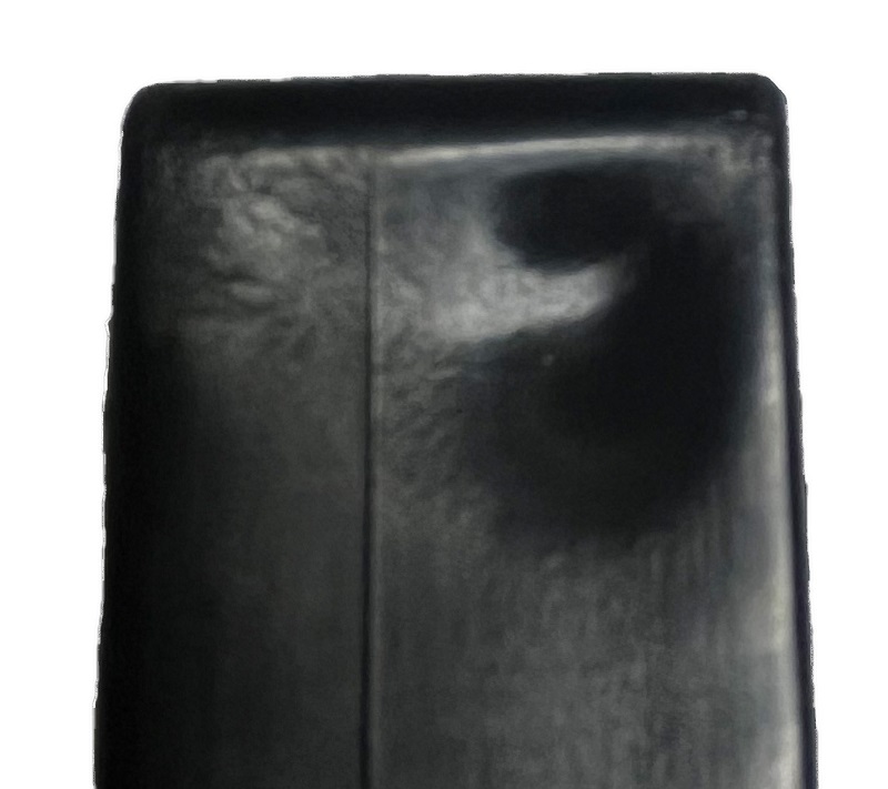
Sink Mark Example
A sink mark happens with plastic design that has particularly thick features which causes the plastic to cool unevenly. If a plastic part has high wall thickness, the outer layer cools and hardens before the molten inner layer. This causes the hardened outer layer to sink into the inner layer, leaving a depression on the surface of the part. This type of surface deformity is also known as a sink mark. To prevent sink or sink marks, consider reducing wall thickness and replacing solid parts of your plastic design with ribs. Including ribs in your plastic part design provides reinforcement to support the flow, strength, and function of the part. Ribs should only be 60-80% as thick as the nominal wall to prevent sink marks where the ribs meet the outer surface of the part. By coring out solid parts in your plastic design, you not only eliminate the cosmetic issue of sink marks, you also use less material overall. This reduces plastic waste and improves part price by reducing cycle time. Cycle time refers to the amount of time it takes to fabricate a complete molded part or series of parts. Plastic designs with thinner nominal wall thickness means parts will cool faster, reducing cycle time so more parts can be produced in a given timeframe. The shorter the cycle time, the higher the profit margin.
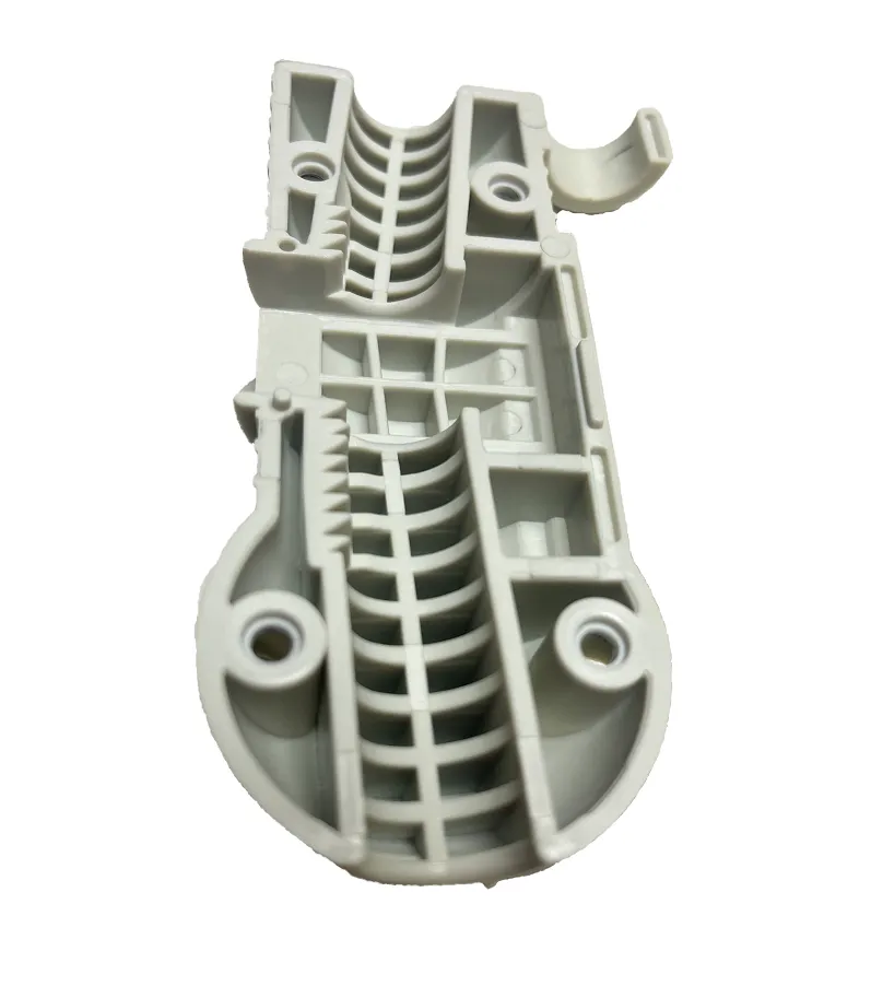
Ribs to Prevent Sink
Voids
Voids in plastic designed parts are air pockets inside the plastic. Voids create a similar cosmetic effect to sink marks, with depressions visible on the surface of the plastic part. Worse, voids compromise the strength of the plastic component. There are a number of ways to prevent voids in your plastic injection parts. Integrated Molding Solutions will evaluate your plastic design and work with your business to make any necessary design changes. Our knowledge allows us to offer non-cosmetic design changes so that the design of the plastic part isn’t compromised for the sake of function. Some ways to minimize or eliminate voids when designing plastic parts are increasing shot size, or the amount of molten plastic that is injected in one molding cycle, increasing plastic injection pressure, and decreasing plastic injection speed. Tooling the mold can also be adjusted to prevent voids.
Part Function in Plastic Design for Injection Molding
Finally, the third component of successful plastic part design for injection molding is part function. The functionality and strength of your plastic design is imperative for a quality product contributing to successful sales. Ribs add strength to plastic parts, as do fillets, radii, and chamfers. A fillet is a plastic design feature that prevents sharp edges in the interior corners of the part by adding a radius, which smooths out or rounds sharp corners in plastic design. Chamfers are 45-degree angles added to the sharp edge or corner of a plastic part design. In plastic injection molds, stress concentrates in sharp corners where pressure from both sides of the corner meets. If the plastic mold design contains sharp corners or sharp edges, that stress is molded into the plastic part, making that area more susceptible to weak spots or breakage. Using fillets, radii, and chamfers in your plastic design strengthens your plastic part and helps prevent breakage from stress.
Gate Design
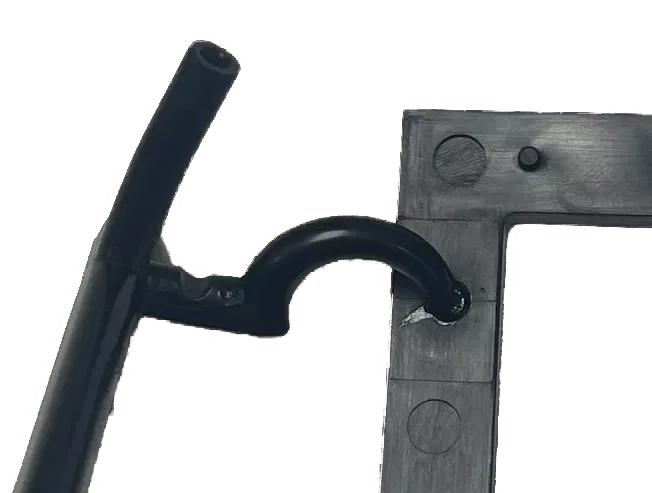
Cashew Gate Example
Gate design is another critical piece of part function in plastic injection molding. The gate is the entry point to the part-forming cavity, where plastic material is injected from the molding machine barrel, through the sprue and runner, into the mold. Gate size can be increased or moved to a section with greater wall thickness to help eliminate voids. If your plastic part design contains different levels of wall thickness, tooling should be adjusted so that the gate is at the thickest wall. Plastic material selection is also important when designing plastics for successful moldability in plastic injection molding. A lower flowing, high viscosity material may help minimize voids in plastic injection molding. Proper gate design for injection molding varies widely depending on part material, part size, and geometry of the plastic design. The bigger the part, the bigger the gate required. IMS will help your business determine the appropriate gate type, size, and location to avoid gate blush in your plastic part design. Gate blush is a deformity that happens when an incorrect gate is used for the part and can result in discolorations or depressions in the plastic around the gate.
Knit Lines
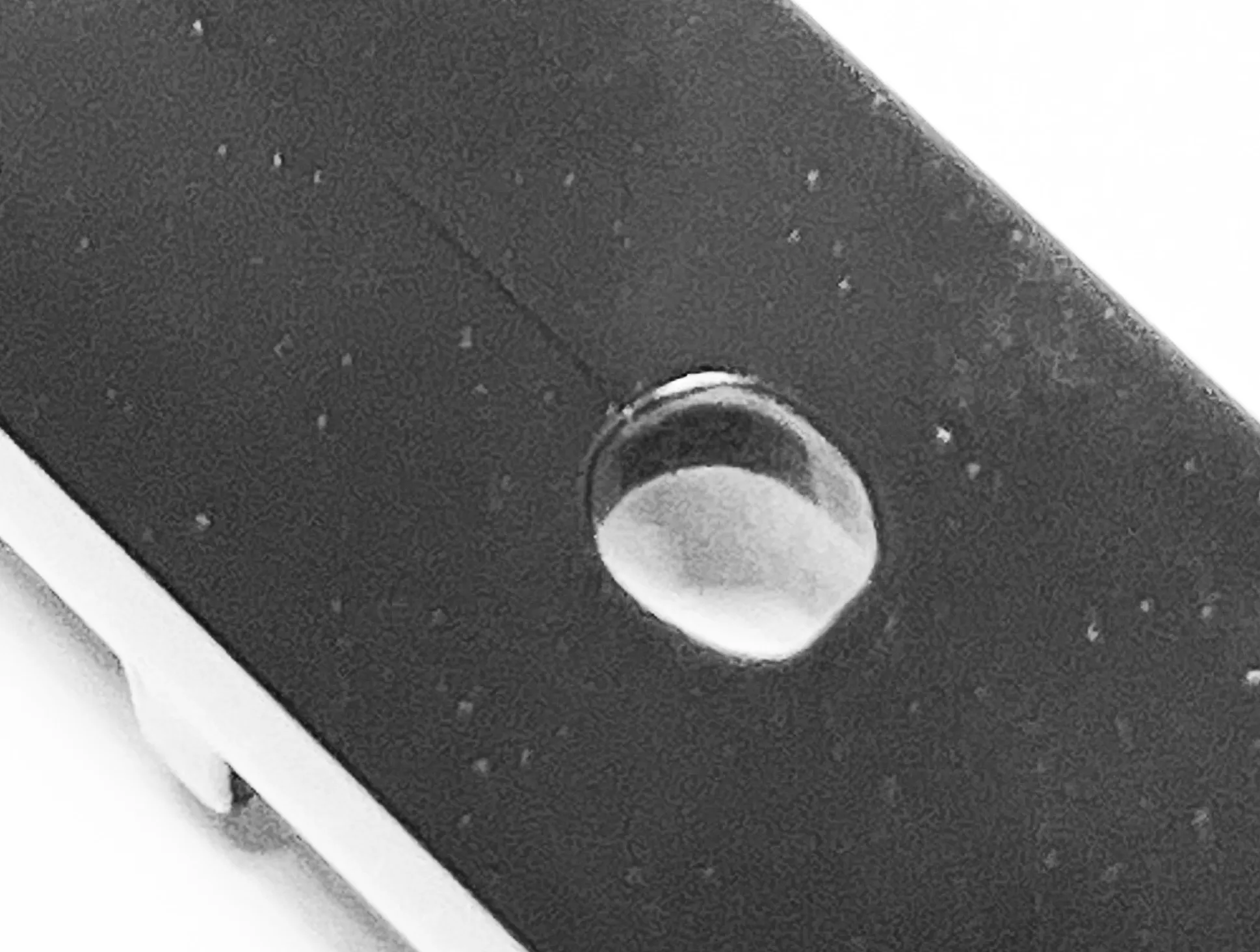
Knit Line Example
Another defect in plastic design caused by incorrect gating are knit lines, which occur in parts with holes in the plastic design. When molten plastic is injected on one side of a hole, it cools down as it travels around the hole. When the slightly cooler flow of plastic meets with the flow of molten plastic on the other side of the hole, the difference in temperature causes visible lines and possibly incomplete bonds in the plastic. Knit lines can be unavoidable if you are designing plastic with holes, but IMS experts will tweak pressures and velocities of plastic injection to prevent knit lines or make knit lines less visible in your plastic part design.
Integrated Molding Solutions engineers are experts in plastic design for injection molding and will work with you each step of the way to maintain the integrity of your vision at a price that keeps your profit margins high. IMS is committed to delivering the highest quality designs and craftsmanship in each plastic component that leaves our plastic factory fabrication floor. Contact us today for all of your plastic product and injection molded part needs.